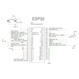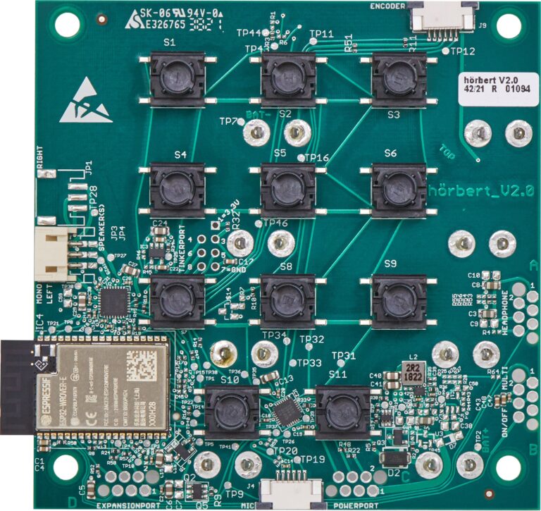
In the past, it was good manners to include a circuit diagram or sketches with every electrical device. We are happy to continue this tradition, because what we were able to learn from circuit diagrams back then has ultimately helped us all.
The electronics of the new hörbert, recognisable by the V2.0 label, uses the ESP32 processor from Espressif. Many interfaces are led to the outside, so that we can offer extensions for hörbert in the future, as we have always done before.
hörbert can be configured in detail with our playlist language PlaLa. We are constantly extending PlaLa with more commands.
Tinkerport
We use the Tinkerport to upload hörbert’s firmware during production. All the signals needed for programming are fed out here. The board does not need an additional power supply via the battery clamps, if you provide a voltage of 3.3V at VCC here. In our production, we use the Tinkerport to program all hörberts with their firmware. We use an FT232R USB-serial adapter for this purpose.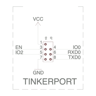
Encoder
As volume control and on/off switch we use a rotary encoder with 24 positions and push function. The signals are directly connected to the ESP32 so that we can also wake up hörbert from deep sleep mode via interrupt without using the ULP.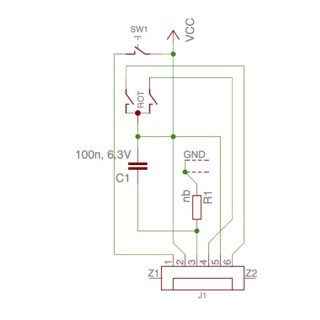
Microphone
We use a PDM (Pulse Density Modulation) microphone SPH0644, whose power supply is directly connected to an LED on our circuit board. If the LED is not lit, the microphone has no voltage and therefore cannot make “secret” recordings.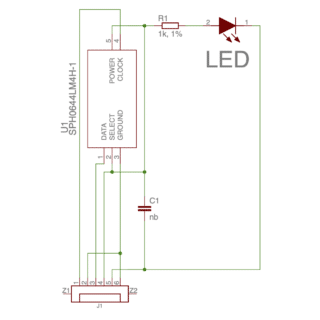
On/Off + Analogue Input
For external control by separate buttons, we run a GPIO and an analogue port to the outside. This allows us to wake up hörbert from deep-sleep mode via interrupt without using the ULP. In addition, further control elements can be queried via the analogue input.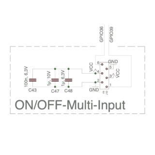
Power port
We have provided the power port for an external power supply. Here, up to 6V can be fed to VBAT_REVPROT, or directly 3.3V to VCC. In addition, the i2c bus and an I/O line of the I/O expander are available here.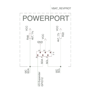
Expansion Port
There are 2 I/O lines available at the expansion port, one of which is connected to the ESP32, the other to the I/O controller. The power supply of the expansion port is switchable, so that external expansions do not have to be permanently supplied with power. Of course, the i2c bus is also connected here.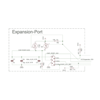
SD card slot
The SD card slot is equipped for 1-bit communication. The Card Detection Switch is connected, but is no longer used in new firmware versions. The Write Protect switch is not connected because SD card extensions and micro SD cards do not support it anyway. Attention, trap! IO2 is connected here, so a programming cable at the Tinkerport can interfere with the function of the SD card.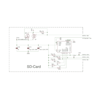
Polarity reversal protection
Reverse polarity protection via FET saves us the voltage drop caused by a diode in series connection.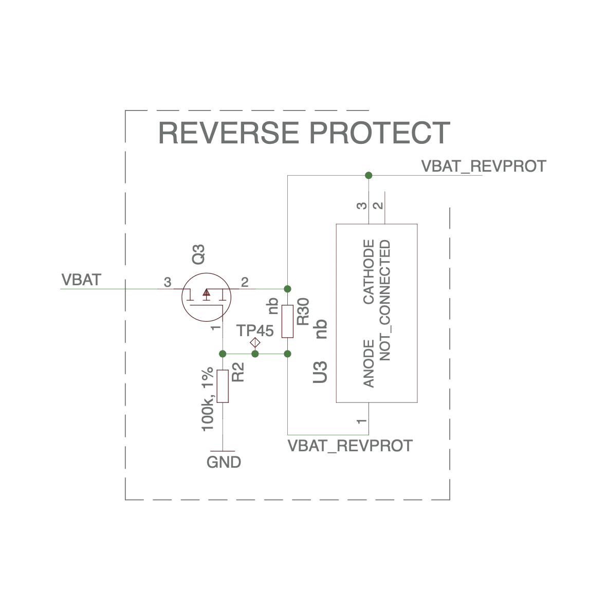
Voltage supply
The highly efficient TPS62902 buck regulator provides 3.3V and eliminates the need for an additional LDO for low loads. This is why the 3V3 LDO is not populated. A 1V8 LDO separately supplies the audio amplifier.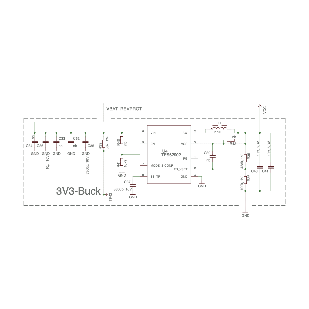
Voltage measurement
For the voltage measurement we use an analogue input of the ESP32 on a voltage divider. We only switch on the voltage divider for measurement in order to save current.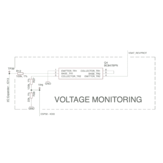
I/O Expander
The I/O Expander SX1503 offers 2 ports with 8 GPIOs. The keyboard matrix (3 columns to 4 rows) is connected here, as well as all signals that no longer have a place on the ESP32.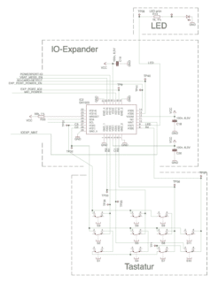
Amplifier
The Class-D amplifier TLV320DAC3120 delivers its mono signal to the loudspeaker(s) and to the wired headphone interface. An alternative configuration with a stereo amplifier is possible, but untested. Stereo headphones can only be connected via Bluetooth, since the amplifier IC is a monoaural version.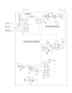
Microprocessor
We use the largest ESP32-WROVER module with 16MB flash to have enough space for future extensions. The ESP32-WROVER module provides WiFi (2.4GHz), Bluetooth (BLE and Classic) via a built-in antenna. We use an i2c bus with 400KHz for communication on the PCB.