esp32: Critical, fatal problem source in some WROVER-E modules

Note: For hörberts sold between October 2021 and February 7th 2022, an immediate firmware update is strongly recommended, See: https://www.hoerbert.com/firmware

All hörberts after 7.2.2022 are not affected

A dormant bug

hörbert’s new electronics, which we have been producing since October 2021 and which hörbert has enriched with many new functions, are based on a very popular and feature-rich processor module. It is the WROVER-E module from the company Espressif. This is a widely used module that is used millions of times worldwide. We use – how could it be otherwise – the module with the largest available built-in flash memory in hörbert, in order to have enough space for our firmware – now and in the future.

Just like you now, we can’t see that there is a bug in the processor module waiting to sabotage the processor module itself.

hoerbert pcb v2.0

Unfortunately, there is a source of error lurking under the bonnet of these modules.

Flash is flash

On the WROVER-E modules, which we buy fully assembled, the processor and two memory chips are located under the shielding metal cover. One of them is the flash memory, on which the firmware remains stored even when the processor module has no power.
As is usual in the market, the manufacturer installs different flash memory chips with different sizes and functions from different manufacturers.

So far, so normal.

The same and yet different

All flash chips used by Espressif have very similar functions and specifications.

One of these functions, which many flash memories have, is write protection, which can be switched on by special commands. The commands to enable write protection differ between products.

And write protection is part of the problem. But only with one of probably 5 interchangeable types of flash chips.

Some of our WROVER-E modules contain a flash chip from XMC. No, unfortunately we cannot know in which modules and in how many hörberts exactly this chip is working, because it is part of the processor module that we cannot produce ourselves. In our case it is the chip XM25QH128C. (->data sheet)

Due to an unknown cause, which Espressif unfortunately has not found yet either, it can happen that the flash chip receives random, perhaps even meaningless commands. These commands completely disable the flash chip. Since the error unfortunately also activates the write protection of this flash chip, it becomes impossible to delete or re-flash it again as a result.
The actual problem is that the corresponding status bits for the write protection are irrevocably set.

This renders the chip useless for all further operations, and it must be physically replaced by us with a new chip.

The solution: Tit for tat!

The Espressif support team sent us a solution in the form of a code snippet, which we immediately integrated into a new hörbert firmware. The pity is: the solution can only prevent the error in advance, before it strikes. The great thing is that the solution prevents the error from happening.

And this is how the solution looks:

Since we don’t know the cause of the error (trash data?), but only the effect (write protection!) is our problem, we prevent the write protection from being set, forever! We don’t need this write protection for hörbert’s functionality, and that’s why we simply slam the door in the face of the source of the error.

So even if the flash chip receives confused commands in the future, it can no longer lock itself.

For programmers

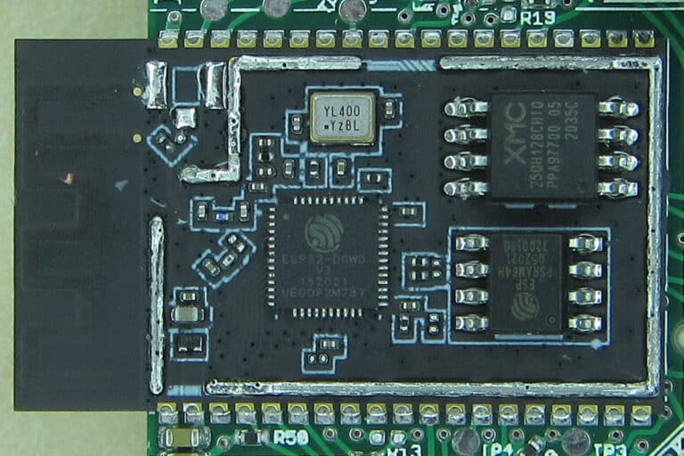
The chip XM25QH128C is connected to the WROVER-E module via SPI. In addition to write and read commands, the three 8-bit wide status registers SR1, SR2 and SR3 can also be set.
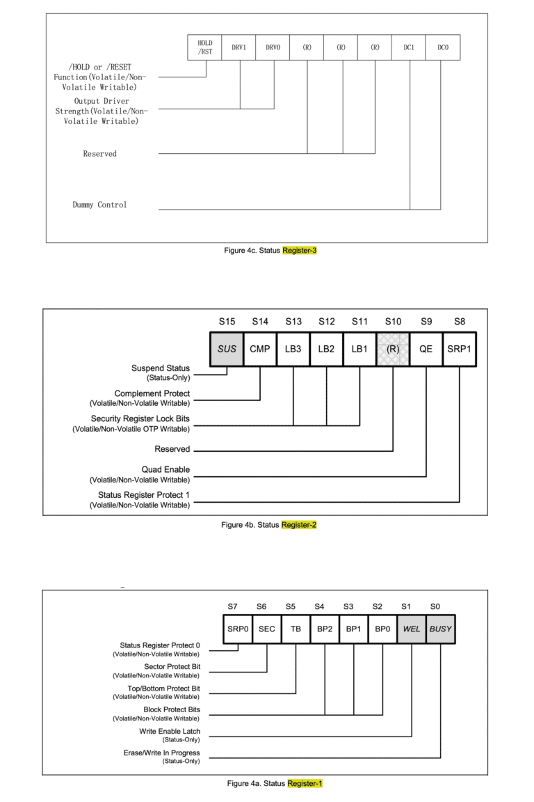
The bits SRP1 (“Status Register Protect 1”) in status register 2 and SRP0 (“Status Register Protect 2”) in status register 1 are responsible for the write protection.

Setting these two bits to “1” blocks the change of all three status registers for all time, because these Status Register Protect bits are “OTP” (one time programmable) bits. Once they are set, they cannot be deleted again. That’s why in our new firmware we set all three status registers to reasonable values that we need for our hörbert, and then set both Status Register Protect bits. This works exactly once.

In our case, we can safely set the registers to the values 0x600380. (S1=0x80, S2=0x03, S3=0x60) These settings are the correct values for our firmware and our functions, and by setting the SRP0 and SRP1 bits, it stays that way.

How do I find out more about the flash chip?

The chip ID can be read out with the help of esptool.py.
In our case it is Manufacturer “20” (XMC) and the Chip ID 4018 (128 MBit Flash).

> esptool.py flash_id
esptool.py v3.1-dev
Found 2 serial ports
Serial port /dev/ttyUSB0
Connecting........_
Detecting chip type... ESP32
Chip is ESP32-D0WD-V3 (revision 3)
Features: WiFi, BT, Dual Core, 240MHz, VRef calibration in efuse, Coding Scheme None
Crystal is 40MHz
MAC: 94:3c:c6:c1:55:e4
Uploading stub...
Running stub...
Stub running...
Manufacturer: 20
Device: 4018
Detected flash size: 16MB
Hard resetting via RTS pin...

The status registers can also be read out with esptool.py. Here is an example of a configured chip with the values of the status registers 0xe37bfc (S1=0xfc, S2=0x7b, S3=0xe3)

> esptool.py read_flash_status --bytes 3
esptool.py v3.1-dev
Found 2 serial ports
Serial port /dev/ttyUSB0
Connecting...
Detecting chip type... ESP32
Chip is ESP32-D0WD-V3 (revision 3)
Features: WiFi, BT, Dual Core, 240MHz, VRef calibration in efuse, Coding Scheme None
Crystal is 40MHz
MAC: 94:3c:c6:c1:55:e4
Stub is already running. No upload is necessary.
Status value: 0xe37bfc
Hard resetting via RTS pin...

What does the error look like on the console?

This is the output you see when the error has already struck and the flash chip has become unusable. The WROVER-E module hangs in an endless boot loop and does not execute any other program except trying to load the second stage bootloader.
ets Jul 29 2019 12:21:46

rst:0x1 (POWERON_RESET),boot:0x33 (SPI_FAST_FLASH_BOOT)
configsip: 0, SPIWP:0xee
clk_drv:0x00,q_drv:0x00,d_drv:0x00,cs0_drv:0x00,hd_drv:0x00,wp_drv:0x00
mode:DIO, clock div:2
load:0x3fff0030,len:380
ho 0 tail 12 room 4
load:0x07800000,len:3378177
ets Jul 29 2019 12:21:46

rst:0x10 (RTCWDT_RTC_RESET),boot:0x33 (SPI_FAST_FLASH_BOOT)
configsip: 0, SPIWP:0xee
clk_drv:0x00,q_drv:0x00,d_drv:0x00,cs0_drv:0x00,hd_drv:0x00,wp_drv:0x00
mode:DIO, clock div:2
load:0x3fff0030,len:380
ho 0 tail 12 room 4
load:0x07800000,len:3378177
ets Jul 29 2019 12:21:46

rst:0x10 (RTCWDT_RTC_RESET),boot:0x33 (SPI_FAST_FLASH_BOOT)
configsip: 0, SPIWP:0xee
clk_drv:0x00,q_drv:0x00,d_drv:0x00,cs0_drv:0x00,hd_drv:0x00,wp_drv:0x00
mode:DIO, clock div:2
load:0x3fff0030,len:380
ho 0 tail 12 room 4
load:0x07800000,len:3378177
ets Jul 29 2019 12:21:46

rst:0x10 (RTCWDT_RTC_RESET),boot:0x33 (SPI_FAST_FLASH_BOOT)
configsip: 0, SPIWP:0xee
clk_drv:0x00,q_drv:0x00,d_drv:0x00,cs0_drv:0x00,hd_drv:0x00,wp_drv:0x00
mode:DIO, clock div:2
load:0x3fff0030,len:380
ho 0 tail 12 room 4
load:0x07800000,len:3378177

... und so weiter ...

Talk is cheap, show me the code!

Disclaimer: Do not use this code for your project if you do not understand which status bits you are allowed to set and which you are not!

This code was fortunately sent to us by Espressif as a basis for our own fix. It requires the esp-idf from Espressif. It runs in RAM and first checks the flash ID 0x204018. Then it reads the status registers and modifies S2 with the absolutely necessary Status Register Protect bit SRP1, and sets bit SRP0, which together make up the actual fix.

#include "freertos/FreeRTOS.h"
#include "freertos/task.h"
#include "soc/spi_reg.h"
#include "esp32/rom/spi_flash.h"
#include "esp_spi_flash.h"
#include "esp_task_wdt.h"
#include "soc/spi_struct.h"

extern uint8_t g_rom_spiflash_dummy_len_plus[];
#define SPIFLASH SPI1

/**
 *  Copy from execute_flash_command() since it is static function
 */
IRAM_ATTR uint32_t bootloader_execute_flash_command(uint8_t command, uint32_t mosi_data, uint8_t mosi_len, uint8_t miso_len)
{
    uint32_t old_ctrl_reg = SPIFLASH.ctrl.val;
#if CONFIG_IDF_TARGET_ESP32
    SPIFLASH.ctrl.val = SPI_WP_REG_M; // keep WP high while idle, otherwise leave DIO mode
#else
    SPIFLASH.ctrl.val = SPI_MEM_WP_REG_M; // keep WP high while idle, otherwise leave DIO mode
#endif
    SPIFLASH.user.usr_dummy = 0;
    SPIFLASH.user.usr_addr = 0;
    SPIFLASH.user.usr_command = 1;
    SPIFLASH.user2.usr_command_bitlen = 7;

    SPIFLASH.user2.usr_command_value = command;
    SPIFLASH.user.usr_miso = miso_len > 0;
#if CONFIG_IDF_TARGET_ESP32
    SPIFLASH.miso_dlen.usr_miso_dbitlen = miso_len ? (miso_len - 1) : 0;
#else
    SPIFLASH.miso_dlen.usr_miso_bit_len = miso_len ? (miso_len - 1) : 0;
#endif
    SPIFLASH.user.usr_mosi = mosi_len > 0;
#if CONFIG_IDF_TARGET_ESP32
    SPIFLASH.mosi_dlen.usr_mosi_dbitlen = mosi_len ? (mosi_len - 1) : 0;
#else
    SPIFLASH.mosi_dlen.usr_mosi_bit_len = mosi_len ? (mosi_len - 1) : 0;
#endif
    SPIFLASH.data_buf[0] = mosi_data;

    if (g_rom_spiflash_dummy_len_plus[1]) {
        /* When flash pins are mapped via GPIO matrix, need a dummy cycle before reading via MISO */
        if (miso_len > 0) {
            SPIFLASH.user.usr_dummy = 1;
            SPIFLASH.user1.usr_dummy_cyclelen = g_rom_spiflash_dummy_len_plus[1] - 1;
        } else {
            SPIFLASH.user.usr_dummy = 0;
            SPIFLASH.user1.usr_dummy_cyclelen = 0;
        }
    }

    SPIFLASH.cmd.usr = 1;
    while (SPIFLASH.cmd.usr != 0) {
    }

    SPIFLASH.ctrl.val = old_ctrl_reg;
    return SPIFLASH.data_buf[0];
}

/**
 * SR3 should be wrote at first before writing SR1 SR2
 */
IRAM_ATTR esp_rom_spiflash_result_t esp_xmc_flash_read_status_sr3(esp_rom_spiflash_chip_t *spi, uint32_t *status)
{
    esp_rom_spiflash_result_t ret;
    esp_rom_spiflash_wait_idle(spi);
    ret = esp_rom_spiflash_read_user_cmd(status, 0x15);
    return ret;
}

IRAM_ATTR esp_rom_spiflash_result_t esp_xmc_flash_read_sr(esp_rom_spiflash_chip_t *spi_flash, uint32_t *sr1_status, uint32_t *sr2_status, uint32_t *sr3_status)
{
    esp_rom_spiflash_result_t ret = esp_rom_spiflash_read_status(spi_flash, sr1_status);
    if (ret != ESP_OK) {
        return ret;
    }
    ret = esp_rom_spiflash_read_statushigh(spi_flash, sr2_status);
    if (ret != ESP_OK) {
        return ret;
    }
    ret = esp_xmc_flash_read_status_sr3(spi_flash, sr3_status);
    if (ret != ESP_OK) {
        return ret;
    }

    *sr2_status >>= 8;
    return ESP_ROM_SPIFLASH_RESULT_OK;
}

/**
 *  Copy from esp_rom_spiflash_enable_write() since it is static function
 */
IRAM_ATTR esp_rom_spiflash_result_t esp_xmc_flash_enable_write(esp_rom_spiflash_chip_t *spi)
{
    uint32_t flash_status = 0;
    esp_rom_spiflash_wait_idle(spi);
    WRITE_PERI_REG(PERIPHS_SPI_FLASH_CMD, SPI_FLASH_WREN);     // Enable write operation
    while (READ_PERI_REG(PERIPHS_SPI_FLASH_CMD) != 0);
    while (ESP_ROM_SPIFLASH_WRENABLE_FLAG != (flash_status & ESP_ROM_SPIFLASH_WRENABLE_FLAG)) {  //Waiting for flash
        esp_rom_spiflash_read_status(spi, &flash_status);
    }
    return ESP_ROM_SPIFLASH_RESULT_OK;
}

IRAM_ATTR esp_err_t esp_xmc_flash_write_sr(esp_rom_spiflash_chip_t *spi_flash, uint8_t sr1_status, uint8_t sr2_status, uint8_t sr3_status)
{
    const uint8_t SPIFLASH_WRSR1 = 0x01;
    const uint8_t SPIFLASH_WRSR2 = 0x31;
    const uint8_t SPIFLASH_WRSR3 = 0x11;

    esp_xmc_flash_enable_write(spi_flash);
    esp_rom_spiflash_wait_idle(spi_flash);
    bootloader_execute_flash_command(SPIFLASH_WRSR3, sr3_status, 8, 0); //SR3 should be wrote at first

    esp_xmc_flash_enable_write(spi_flash);
    esp_rom_spiflash_wait_idle(spi_flash);
    bootloader_execute_flash_command(SPIFLASH_WRSR1, sr1_status, 8, 0);

    esp_xmc_flash_enable_write(spi_flash);
    esp_rom_spiflash_wait_idle(spi_flash);
    bootloader_execute_flash_command(SPIFLASH_WRSR2, sr2_status, 8, 0);
    esp_rom_spiflash_wait_idle(spi_flash);
    return ESP_OK;
}

/**
 * One time programming, the status register value will be programmed into 0x600380(little-ending) and can't be reversed
 */
IRAM_ATTR esp_err_t esp_xmc_16m_flash_sr_otp(esp_rom_spiflash_chip_t *spi_flash)
{
    if (spi_flash->device_id != 0x204018) {
        return ESP_ERR_NOT_FOUND;
    }
    uint32_t sr1_status = 0;
    uint32_t sr2_status = 0;
    uint32_t sr3_status = 0;
//    const uint8_t SR1_TB_MASK = 0x20;       //Top/Botton protect bit (SR1 bit5), Should be cleared
//    const uint8_t SR1_BP_MASK = 0x1c;      //Block protect bits, include BP0(SR1 bit4), BP1(SR1 bit3), BP2(SR1 bit2), should be cleared
//    const uint8_t SR1_SEC_MASK = 0x40;    //Sector protect bit(SR1 bit6), should be cleared
//    const uint8_t SR1_WEL_MASK = 0x02;   //Write enable latch(SR1 bit1), should be cleared
    const uint8_t SR1_SRP0_MASK = 0x80;   //SRP0, Should be set
    const uint8_t SR2_SRP1_MASK = 0x01;  //SRP1, Should be set
    const uint8_t SR2_QE_MASK = 0x02;   //Quad Enable,

    esp_rom_spiflash_result_t ret = esp_xmc_flash_read_sr(spi_flash, &sr1_status, &sr2_status, &sr3_status);
    if (ret != ESP_ROM_SPIFLASH_RESULT_OK) {
        return ESP_FAIL;
    }
    if ((sr1_status & SR1_SRP0_MASK) && (sr2_status & SR2_SRP1_MASK)) {
        //SPR0 and SPR1 has been set
        return ESP_OK;
    }
    uint8_t new_sr1_status = 0x80;  //Set SRP0, clear other protect bits
    uint8_t new_sr2_status = ((uint8_t)sr2_status | SR2_SRP1_MASK | SR2_QE_MASK);
    uint8_t new_sr3_status = 0x60;
    esp_xmc_flash_write_sr(spi_flash, new_sr1_status, new_sr2_status, new_sr3_status);
    return ESP_OK;
}

IRAM_ATTR void app_main(void)  //app_main should be put into IRAM
{
    esp_err_t ret;
    TaskHandle_t cur_core_idle_handle = xTaskGetIdleTaskHandle();
    ret = esp_task_wdt_delete(cur_core_idle_handle);  //Disable watchdog
    if (ret != ESP_OK) {
        return;
    }
    g_flash_guard_default_ops.start(); //Disable cache
    esp_xmc_16m_flash_sr_otp(&g_rom_flashchip);
    g_flash_guard_default_ops.end();  //Enable cache
    ret = esp_task_wdt_add(cur_core_idle_handle);
    if (ret != ESP_OK) {
        return;
    }

    while (1) {
        vTaskDelay(pdMS_TO_TICKS(1000));
    }
}

The method becomes more understandable if you take a look at the status registers of the flash chip.

The status registers of the flash chip used

* Prices including 19% VAT